• Status flag diagnosis with current sense capability
• Protection e.g. against overtemperature and overcurrent
• Reverse polarity protection with IPD90P04P4L
• Further comments:
- Due to limited performance caused by the PCB layout, we recommend our customers to remove thecapacitance C5 for high frequency applications. It is only layout related, not refer to the device.
- The size of the DC-link capacity (C4 in schematic) with 560 μF is for most applications sufficient. But forhigh current applications, we recommend our customers to follow the design rule in our applicationnote and replace the DC-link cap with a bigger one.
- Due to the limited area of the PCB and the small DC-link cap, the demoboard shouldn’t be used forshort circuit test.
- This demoboard is designed for both sensorless applications and the application with Hall sensor. Butfor the application with sensor, please remove R36/R37/R38 and solder R18/R19/R20/R21/R22/R23/R25/R26/R27.
- Due to the limited pinout of the Arduino shield all IS pins of the three devices are connected together.According to different applications the value of R4 could be adjusted to achieve a better current sense performance.
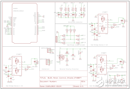
图5.马达控制板电路图
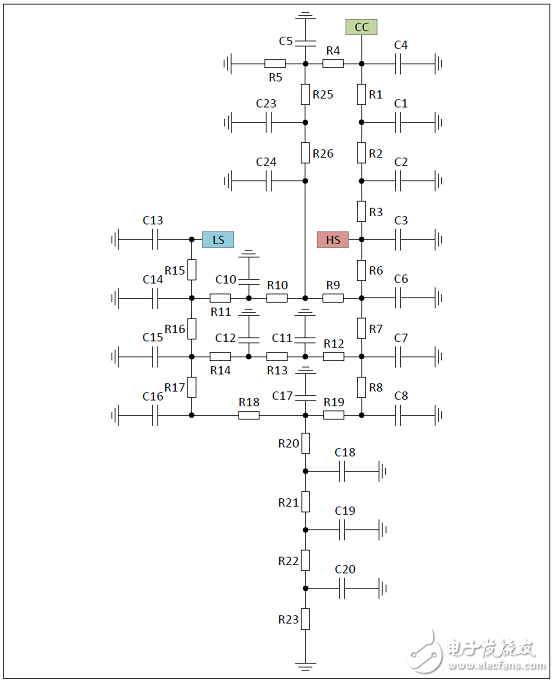
图6.IFX007T热RC网络电路图
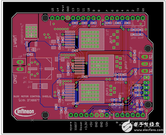
图7.马达控制板PCB设计图:Arduino和IFX007T
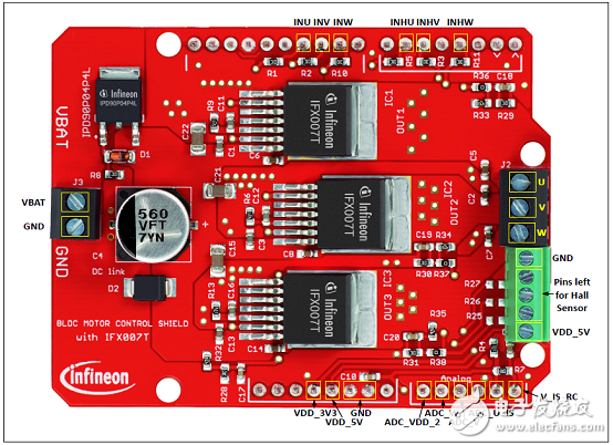
图8.马达控制板PCB设计图:连接器
关于控制,MCU就介绍完了,您有什么想法可以联系小编。


